Gridspective Documentation
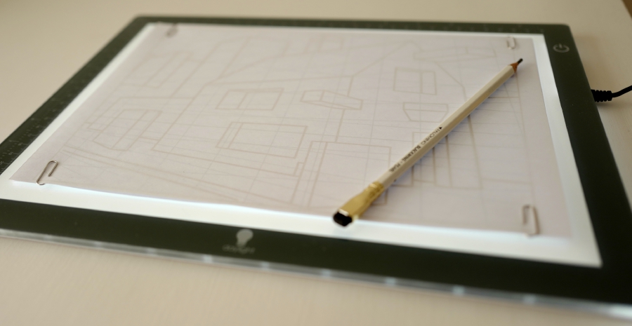
Gridspective is an online utility that allows you to create an image with perspective grids and additional construction lines. The image can then be printed and used as an underdrawing on a lightbox for example.
The aim is to help speed up the process of creating perspective grids and construction lines as a basis for a drawing using traditional materials. The grids and construction lines can be placed quickly and it doesn't matter if the vanishing points are far away from the page.
Note that Gridspective has currently only been tested on Chrome, Firefox and iPad.
Launch Gridspective
Quick overview
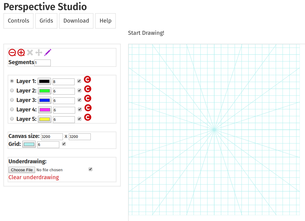
There is one main view, with a settings pane to the left and a canvas to the right. The canvas is the image that you can draw on.
When clicking on one of the tabs on the left settings pane, different settings panes will pop up.
- "Controls" : this tab allows you to configure how the image is drawn: sizes, line colors, underdrawings and such.
- "Grids" : The Grids tab allows you to configure the perspective grids and how line placement will interact with them.
- "Download" : When the drawing is finished, the image can be downloaded. Alternatively, a textual representation can be downloaded for future re-use.
- "Help" : This pane brings you back to this page and other documentation, tutorial and example pages.
The "Controls" tab
On this tab are a few control groups. The first one allows you to choose an operation:and allow you yo zoom in or out on the canvas (for detailed work, or to see an overview of the entire canvas).
Delete line segments.
Move the canvas.
Draw lines. When lines from the same layer cross each other, they are split into segments from the point where they intersect. You can then remove segments later. So it is a good idea to over-shoot your lines, because you can easily remove residual line segments later.
When drawing lines, you can specify how many segments the line should be divided into. This allows you to quickly lay out a grid that starts from a line that runs perpendicular to the viewing direction. You can, for example, draw a horizontal line with eight segments, and quickly construct an eight-head-high human represented by eight stacked boxes that way, or you can quickly create a grid that allows you to place windows and doors on the front of a building.
These modes can also be chosen quickly by pressing the keys 'L' for Draw mode, and 'D' for Delete mode and 'M' for Move Canvas Mode.
The next control group allows you to set the current layer you want to draw on, the line color and line width for that layer, and whether you see it. The icon to the right of it allows you to remove all line segments from that layer.
Below that, you can change the Canvas size in pixels - the width X the height. To determine what works best for you, these are the considerations:
- You should choose a size - width and height - so that the aspect ratio matches that of the final image you want to draw.
- You want the size to be as big as possible, for a better resolution, but at the same time not too unwieldy.
You can also set the color and line width for the perspective grid.
While drawing, the cursor will try to snap to end points in the current layer and it will try to draw towards one of the vanishing points. In addition, above the canvas, a notification will show the current position on the canvas and the drag distance: the length the line currently has. This can help with precise placement.
Underdrawing specifies an optional image to be placed under the canvas. This allows you to reconstruct the horizon and vanishing points from that image, and to place construction lines based on that image. The image can be a photo, but it can also be a rough pencil sketch, a design for what the image will ultimately look like. This image can be loaded from a file, or cleared through the Clear underdrawing link.
The "Grids" tab
Through Number of vanishing points you can choose how many vanishing points to use: one-, two- or three-point perspective is currently supported.The Horizon level is also set in pixels. If the image is 400 pixels high, setting the horizon to 200 will place it in the middle of the image, placing it at 400 will put it at the bottom of the image.
The horizon should usually be somewhere on screen, so its value should generally be between zero and the height of the canvas. Except when dealing with three-point perspective. In that case, the horizon will most likely be below the canvas if the third vanishing point is high, and vice versa. When the three-point perspective is chosen, the center of view is calculated and shown and turned into a red warning if it falls outside the screen. In that case, it is probably a good idea to adjust the horizon and the y position of the third vanishing point.
The vanishing point x values vp #1, vp #2 and vp #3 are the x values, also in pixels. If the canvas is 600 pixels wide, putting a vanishing point at zero will put it at the left edge of the image, putting it at 300 will place it in the middle, and placing it at 600 will put it at the right edge of the canvas.
Vp #3 y is a special case. It sets the y coordinate for the third vanishing point, which will not be on the horizon like the first two vanishing points.
The values for Nrs1, Nrs2 and Nrs3 determine how fine the perspective grids need to be drawn. When the vanishing point exists, the value for its Nrs determines how many lines will be drawn radiating from that vanishing point. So the smaller the number, the less dense. If that vanishing point is not drawn, horizontal or vertical lines will be drawn on its behalf, and Nrs determines the number of pixels between grid lines, and in this case, the smaller the number, the denser the grid (which is the opposite of when it does have a vanishing point).
Rotations.
Two rotations are supported right now. Rotation rotates the vanishing point certain degrees. This is helpful in placing lines that are rotated from eachother but that adhere to vanishing points that are consistent.
The rotation is done as follows: first a line is dropped down from the horizon line, at the middle of the panel. On this line, the code tries to find that point such that the lines from that point to both the vanishing points on the horizon are at an angle 90 degrees from each other. This point is the "Station Point" and it is the point where the viewer is standing, and it is the point where angles don't change. As the two vanishing points represent directions, they are at an angle of 90 degrees in the world, and so they are at an angle of 90 degrees at the Station Point also.
After the rotation, Tilt tilts the horizon a certain amount of degrees.
A cool trick you can do with rotation: if you rotate the ground surface by 45 degrees, the vanishing point in sight will be the diagonal vanishing point. Lines through this point are diagonals of squares and this allows you to create precise squares on the ground plane.
Snapping to grids or end points
When drawing lines, it is useful if the line can snap to one of the perspective grids. This is enabled by default, through the Perspective grid checkbox, which can also be toggled through typing 'G'.
Also, when near the end of a line, it may be desirable that the mouse snaps to that point. This is also enabled by default by the End points checkbox, which can be toggled by pressing 'E'. When snap to end points is enabled, they are also shown on the canvas.
By default, the cursor will snap to end points on any layer, but this can be turned on or off with the "Snap to all layers" checkbox.
The Snap distance field determines the maximum distance in pixels within which to allow for snapping.
The "Download" tab
If you click on the Download png image link, the canvas will be saved as 'grid.png'. Pressing 'S' also takes a snapshot of the current canvas. This is useful if you want to take a snapshot while interacting.The downloaded 'grid.png' image is the whole point of this utility: you can print it out and place it underneath a piece of paper on a lightbox and use the perspective grid and construction lines as guides while drawing.
Clicking the Data checkbox reveals the drawing as represented in a textual format. If you copy the text and place it in a file with extension .json, you can use it later (perhaps possible only if you are running this utility locally). If you saved it to the file 'mydrawing.json' for example, you can append the following after the url: "?model=mydrawing" next time you load the page, and the model will be loaded again.
It is a bit of a complicated construct, but that is because this utility has been written in Javascript, and Javascript (rightly) doesn't allow reading and writing files.
The "Help" tab
The help pane refers you to this and possibly other documentation.
Quick summary of hotkeys:
- L : Draw mode (draw lines)
- D : Delete mode (delete line segments)
- M : Move Canvas Mode
- G : Toggle snap to perspective grids
- E : Toggle snap to end points
- S : Take snapshot of canvas
That's it, really!
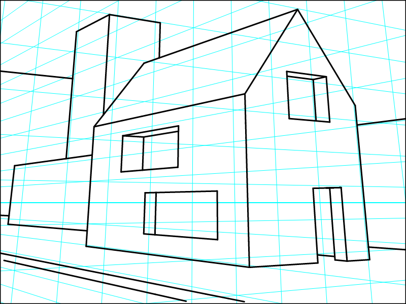
Example: Drawing a house with a pointed roof
This short quick tutorial, in which I draw a house with a point roof, doors and windows and some other fore- and background, shows some of the things you can do with vPoint.
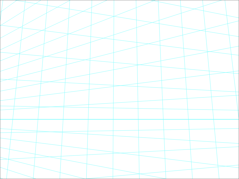
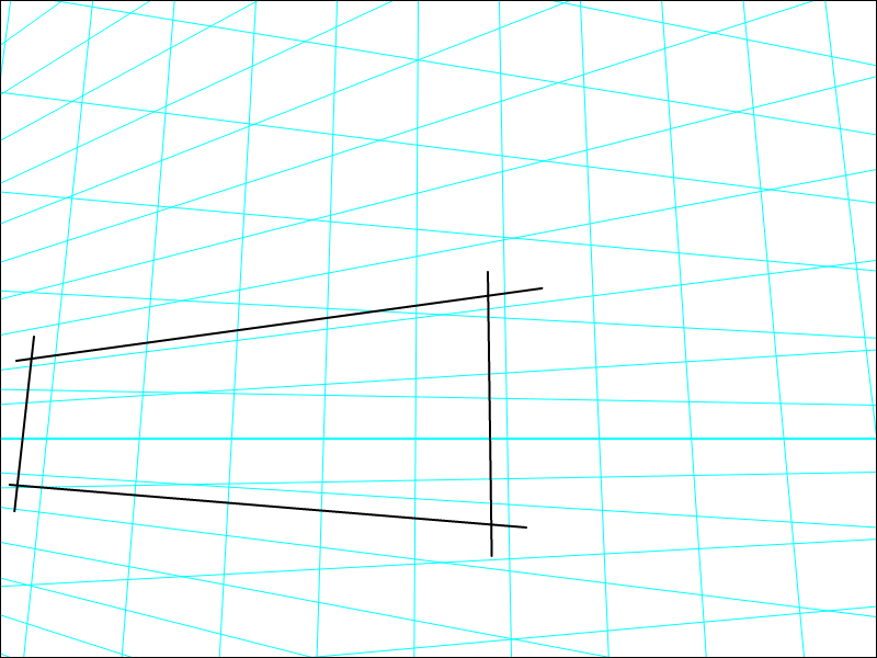
 I started with a 3-point perspective grid, and I made a quick sketch (in red) in vPoint itself, determining where roughly I wanted the blocks. I then used that quick sketch as the underdrawing, a guide to reference from.
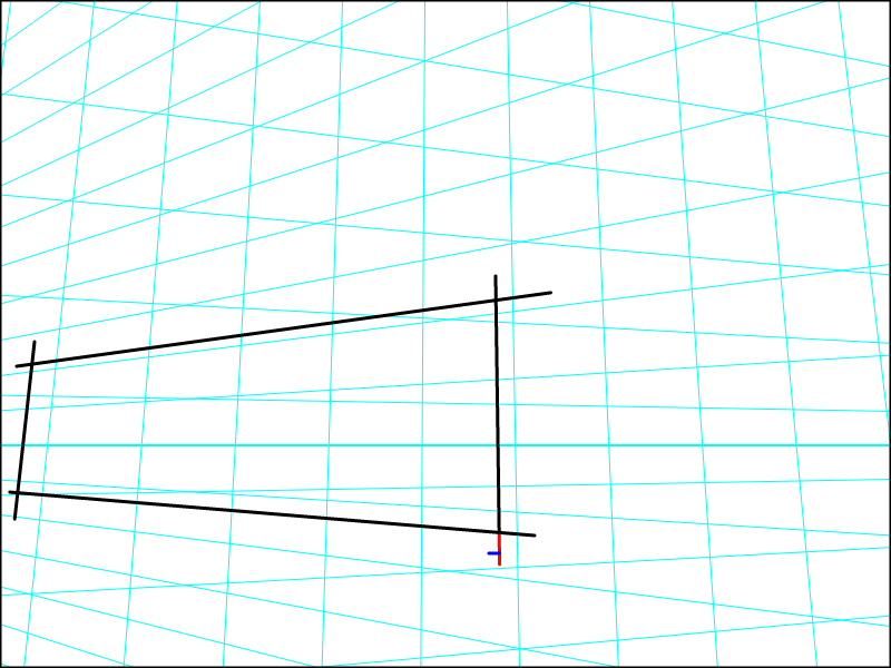
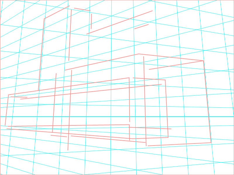
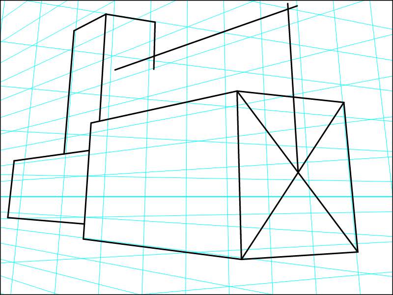
Here you see the first side of a block. As you can see, I overshot the construction lines considerably. I did this because it helps me to more easily select the line segments that I want removed (see blue and red line highlights). This is a common way to draw with vPoint: draw lines, let them intersect, then remove the line segments you don't want.
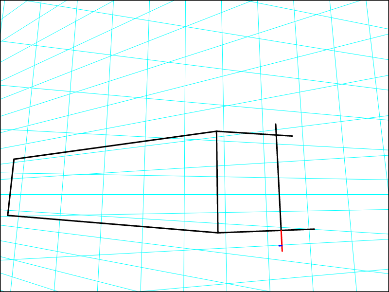
Here the blocks overlap. But the same principle applies: I can remove parts of the block that fall behind another block easily by removing the line segments that disappear behind that block.
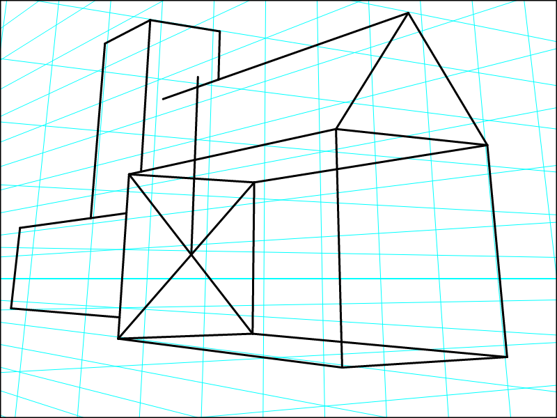
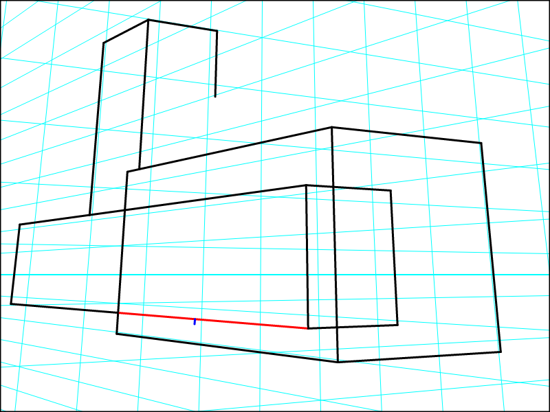
Here I used an 'x-marks-the-spot approach to find the middle of the front pane of the house. I did this by disabling snapping to the perspective grid so I could draw lines in any direction. Then I turned 'snap to perspective' back on again, and drew a line to the third vanishing point. This is the tip of the roof. Then again with snap to perspective turned off, I drew the sides of the roof.
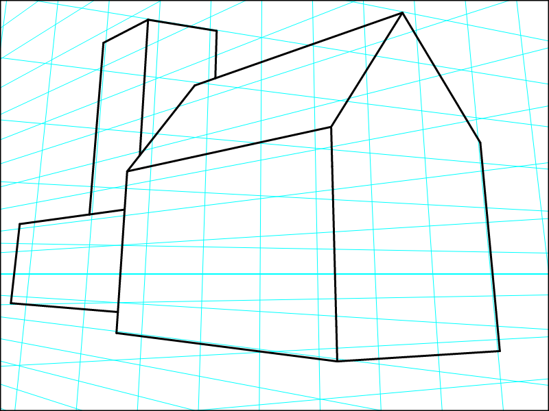
The same was done with the back pane of the block that represents the body of the house, drawing construction lines that I remove again afterwards.
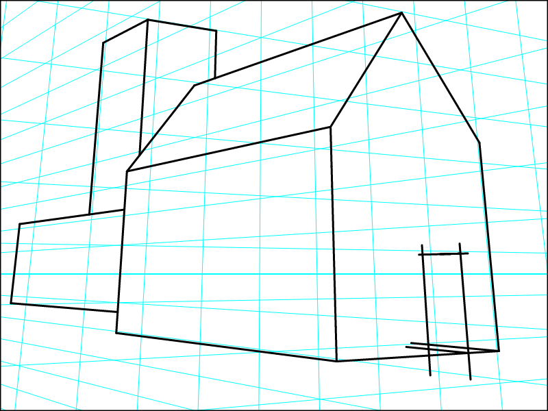
The same tricks can be used to cut parts out of blocks, like windows and doors.
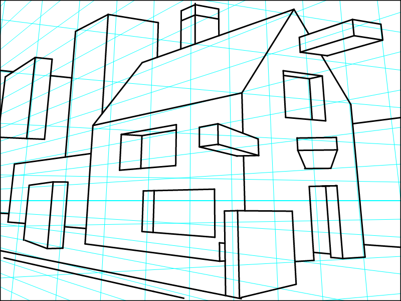
And finally I had some fun using 'Rotation' to rotate the vanishing points in the ground plane in such a way that they stay consistent with the original vanishing points, and I drew some more blocks.
And it is ready to be printed out and placed behind a clean sheet of paper on a lightbox, to be used as a guide while penciling in a scene.